
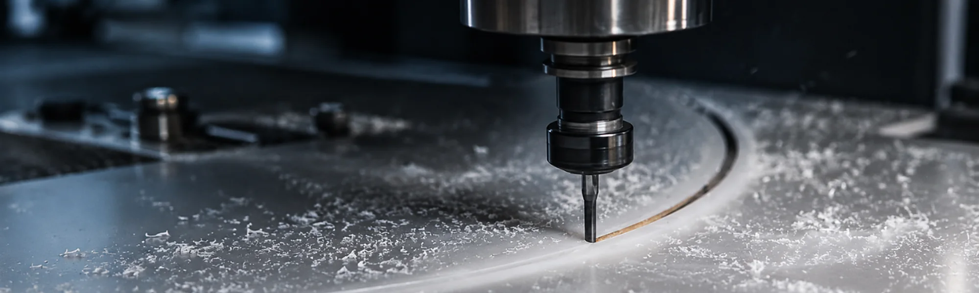
CNC machining of engineering plastics
Machine the features.Control the datums.
Plastic prototypes, project-specific small series and post-processing of moulded or formed parts — planned around the material, geometry and required result.
- PrototypesBefore production tooling
- Small seriesProject-specific quantities
- Post-processingMoulded and formed parts
- Part-specificDimensions and tolerances agreed
CNC machining of plastics
Cut only what thefunction requires.
CNC machining can create a functional prototype, produce a project-specific small series or add openings, interfaces and precision features after moulding or forming. The route starts with the drawing, material grade and the features that matter.
Part purpose
Define the function and intended use.
Material grade
Select the correct grade and condition.
Critical features
Identify datums and key dimensions.
Next operation
Consider joining, assembly or packaging.

- Datum
- Critical bore
- Mating face
- Check point
Where CNC adds value
Three routes. Different production intent.
Functional prototypes
Evaluate geometry, interfaces and assembly before committing to production tooling.
DISCUSS THE PARTProject-specific small series
Direct machining for quantities and applications agreed for the project.
DISCUSS THE PARTThe drawing must definewhat matters.
Critical dimensions need a clear relationship to the functional surfaces and adjoining components. Fixture strategy, tool access and inspection all depend on that definition.
Material
Exact grade and condition
Datums
Functional reference surfaces
Tolerances
Critical features identified
Surface
Finish and visible areas
Tool access
Reach and clearance
Fixturing
Stable support without damage
Edges
Burr and edge requirements
Assembly
Mating parts and next stage
Feasibility and tolerances are agreed for the specific material, geometry, fixture concept and required surface condition.
A controlled machining route
From part data to inspected component.
- 01
Define
Function and critical features
- 02
Review
Material, geometry and tolerances
- 03
Program
Toolpaths and machining sequence
- 04
Fixture
Support and datum strategy
- 05
Machine
Controlled feature creation
- 06
Inspect
Agreed dimensions and surfaces
The machining and inspection plan follows the drawing and the agreed production intent.
Engineering plastics need material-aware machining
The material influencesthe method.
Plastic behaviour can vary with grade, temperature, moisture, wall section and internal stress. Tooling, clamping and cutting strategy must be selected for the actual material and component.
POM
Dimensional and mechanical applications
PC
Transparent or impact-related applications
PEEK
Demanding engineering applications
Other plastics
Reviewed by exact grade and requirement
- Cutting heat
- Chip evacuation
- Part support
- Surface condition
Material names alone are not enough — provide the exact grade where known.
Design for access, support and inspection
A feature must be reachable — and measurable.
Openings
Position and edge relationship
Pockets
Tool reach and corner geometry
Thin walls
Support during machining
Deep features
Access and chip removal
Mating faces
Datums and flatness intent
Internal radii
Tool geometry considered
Do not assign unnecessarily tight tolerances to every dimension. Identify the features that control fit, function and assembly.
CNC can be one stage in a larger route.
A moulded or formed component can be machined before sealing, joining, assembly or packaging. Reviewing the complete sequence helps keep datums, visible surfaces and interfaces aligned.
- Mould / form
- CNC machine
- Clean & check
- Assemble
- Pack
A machined prototype is useful —but not identical to a moulded part.
Machining can validate size, interfaces and assembly. Material condition, fibre orientation, residual stress, surface and manufacturing history may differ from a future moulded component.
- Use prototypes to review fit and function
- Record what must carry into production
- Reconfirm production-part acceptance
Machined prototype
Moulded production part
- Geometry
- Interfaces
- Function
- Material history
- Surface
Inspection follows the function
Check the features that control the part.
Dimensions
Critical features and datums
Surfaces
Visible and functional areas
Edges
Burr and handling requirements
Assembly
Fit with adjoining components
ISO 9001 | ISO 14001 | AQAP 2110
Measurement method and acceptance criteria are agreed for the part.
Start with the part data
Send the drawing, materialand required result.
If the specification is incomplete, send the available information and identify the part’s function.
Part information
- Dimensioned 2D drawing and 3D model
- Exact material grade where known
- Prototype, small-series or post-process intent
- Expected quantity
Technical requirements
- Critical dimensions and tolerances
- Datums, visible and mating surfaces
- Surface and edge requirements
- Subsequent assembly or production stages
CNC plastic machiningquestions
CNC machining can be used for functional prototypes, project-specific small series and post-processing of moulded or formed plastic parts. The suitable route depends on the component, material, required features and production intent.
Identify critical dimensions, datums and functional interfaces on the drawing. Achievable tolerances depend on the plastic grade, component geometry, fixture strategy, surface requirement and agreed measurement method.
Yes. CNC machining can add openings, trimmed edges, mating surfaces or other defined features after injection moulding, rotational moulding or vacuum forming. The complete production sequence should be reviewed before machining is specified.
Not necessarily. A machined prototype can help evaluate geometry, fit and assembly, but its material condition, fibre orientation, residual stress, surface and manufacturing history may differ from those of a moulded production component.
Have a plastic part to machine?
Send the model — and show us what matters.
Share the drawing or 3D model, material grade, quantity, critical dimensions and the intended next stage.