
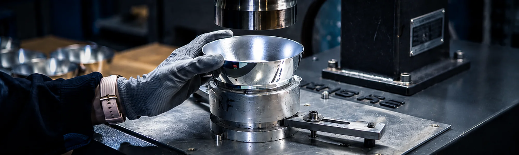
Ultrasonic Welding of Thermoplastic Parts
Join the parts.Control the interface.
Ultrasonic joining reviewed as part of the complete moulding and assembly route — including material pairing, joint geometry, support, assembly sequence and acceptance criteria.
- Thermoplastic joiningMoulded components and housings
- Joint designMaterials and geometry reviewed together
- Assembly sequenceInserts, gaskets and components considered
- Acceptance criteriaSpecified for the finished assembly
The weld is part of the component design
Design both parts andthe interface together.
Ultrasonic welding depends on the complete assembly. Materials, mating surfaces, joint features, wall support, access and the components present during welding must be reviewed as one system.
Material pair
Exact grades where known
Joint geometry
Mating surfaces and weld feature
Part support
Stable location during joining
Assembly content
Inserts, gaskets and electronics
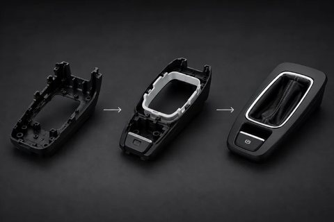
Welding suitability is confirmed for the specific material combination, part geometry and tooling concept.
Designing the welded joint
The drawing must definethe complete interface.
Provide both components and identify the characteristics that determine whether the assembled joint is acceptable.
Mating surfaces
Show the full contact and joining area.
Weld feature
Define the geometry intended to concentrate energy.
Wall & flange support
Support the joint during the welding cycle.
Tool access
Provide access for the horn and fixture.
Part location
Control alignment between both components.
Nearby features
Identify inserts, gaskets and sensitive parts.
A welding process cannot compensate for incompatible materials or a joint that has not been designed for the required result.
A controlled joining route
From part data to approved assembly.
- 01
Define
Function, loading and assembly requirements
- 02
Review
Materials, joint and surrounding features
- 03
Tool
Horn, support and part location considered
- 04
Join
Vibration and force applied at the interface
- 05
Sample
Assemblies reviewed against agreed criteria
- 06
Produce
Serial joining and documentation scope
Process settings, inspection and acceptance requirements are defined according to the project.
How the joint is created
Energy must reachthe intended interface.
Ultrasonic vibration is directed through the components and converted to heat at the joining interface. The joint depends on material pairing, part design, energy path and proper support during the welding cycle.
Energy path
Directed through the component to the joint
Contact
Mating surfaces positioned as designed
Support
Assembly held against the applied load
Local joining
Heat generated at the intended interface
Actual joint performance must be established through the agreed sample and acceptance route.
Materials must be reviewed as a pair
Do not assume two thermoplastics will weld.
Identify the material of both components, including the exact grades where known. Suitability depends on the specific combination, part design, joint geometry and manufacturing condition.
Upper component
Material and grade
Lower component
Material and grade
Interface condition
Surface and moulded quality
Part geometry
Distance and path to the joint
Application
Loading and operating conditions
Material names alone are not sufficient to guarantee compatibility or joint performance.
Tooling & assembly sequence
What is inside thehousing matters.
Include inserts, gaskets, electronic components and other elements that will be present when the housing is joined. Their position and sensitivity help define the proposed assembly sequence.
- 01
Locate
Both moulded components aligned
- 02
Support
Fixture supports the joint area
- 03
Protect
Sensitive contents considered
- 04
Join
Welding occurs at the defined interface
Define the required result
Acceptance belongs tothe finished assembly.
Joint acceptance
State the required joint strength, dimensional checks, appearance criteria and any functional requirements. The inspection scope is agreed for the project.
- Joint strength requirement
- Critical dimensions
- Visible-surface criteria
- Functional assembly checks
Enclosure protection
Ultrasonic welding alone does not establish an IP rating. Water- or dust-protection requirements concern the complete enclosure and final assembly conditions.
- Housing and cover
- Welded joint
- Openings and interfaces
- Gaskets, inserts and hardware
Any leak-tightness or IP requirement must be verified on the complete finished enclosure under specified conditions.
Moulding, joining and assembly
Plan the completecomponent before production.
Ultrasonic welding can be considered alongside moulding, CNC machining, foam gasketing and assembly. The route depends on the component and its agreed requirements.
Plastic moulding
Both components produced to the approved design.
CNC machining
Post-processing where the agreed geometry requires it.
FIPFG gasketing
Separate sealing operation where suitable.
Ultrasonic welding
Components joined at the designed interface.
Assembly & packaging
Final completion within the agreed scope.
What to send for a review
Start with both parts,materials and joint requirements.
Part & material data
- 2D drawings and 3D models of both parts
- Material and grade for each component
- Complete joint and mating surfaces
- Critical dimensions and visible surfaces
- Inserts, gaskets and internal components
Project requirements
- Intended function and loads
- Expected annual quantity
- Required joint strength
- Leak-tightness or enclosure target
- Inspection, assembly and packaging scope
- ISO 9001
- ISO 14001
- AQAP 2110
Ultrasonic weldingquestions
Ultrasonic vibration is directed through the components and converted into localised heat at the designed joining interface. The parts are positioned and supported by tooling while the joint is formed. The suitable process route depends on the materials, joint geometry, energy path and assembly.
Provide drawings and 3D models of both parts, the exact material grades where known, mating surfaces, intended weld feature, critical dimensions and assembly requirements. Include any inserts, gaskets, electronics or other internal components.
A leak-tight or protected enclosure may be a project requirement, but welding alone does not establish an IP rating. The complete housing, welded joint, openings, gaskets, inserts and final assembly conditions must be considered and the required result verified under specified conditions.
Where suitable and included in the agreed project scope, the route may include injection moulding, CNC machining, FIPFG gasketing, ultrasonic welding, final assembly and packaging. The complete sequence should be identified during the initial review.
Have a thermoplastic assembly in mind?
Send both parts and the joint requirements.
Share drawings of both components, material grades, expected quantity and the required joint strength or leak-tightness. Include inserts, gaskets, electronics and the complete assembly specification.