
Rotational Moulding in Estonia
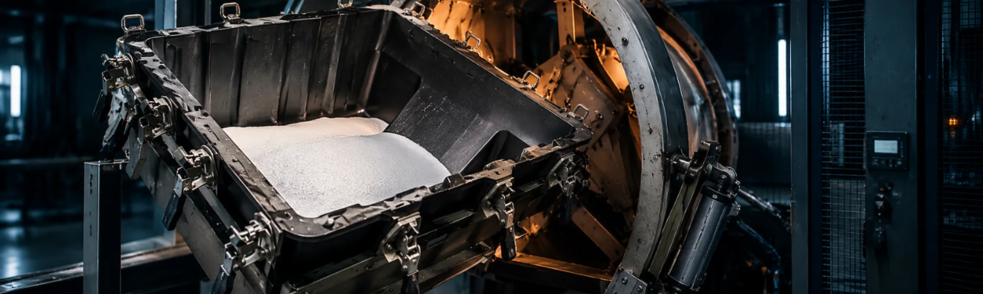
Hollow components.Moulded in one piece.
Polyethylene tanks, containers, chambers and housings — reviewed from part geometry and material through tooling, moulding, machining and final assembly.
- One-piece mouldingHollow components without assembled shell halves
- Polyethylene partsMaterial grade selected for the project
- Geometry-ledWall requirements and features reviewed together
- Finish & assemblyOpenings, fittings and final operations
When rotational moulding fits
Design the hollow partas a complete system.
Rotational moulding forms a hollow component inside a rotating mould. Part size, shape, wall requirements, openings, fittings, material and operating conditions must be reviewed together.
Hollow geometry
Tanks, containers and housings
One-piece part
Shell produced as a single moulding
Wall requirements
Defined for the application
Follow-up work
Machining, fittings and assembly
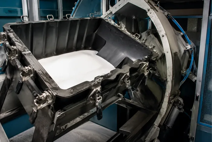
Process suitability is confirmed for the individual part, material and tooling concept.
How rotational moulding works
From material in the mould to one-piece component.
- 01
Define
Function, contents and operating conditions
- 02
Review
Geometry, material and wall requirements
- 03
Tool
Mould and production route prepared
- 04
Heat & rotate
Material distributed inside the rotating mould
- 05
Cool & release
Formed component removed from the tool
- 06
Finish
Openings, fittings and assembly completed
The exact tooling, process and acceptance criteria are defined according to the project.
Design the part for the process
The internal and externalgeometry work together.
The moulded wall follows the complete part shape, so transitions, features and access for subsequent operations must be considered from the start.
Wall requirements
Define what the application requires.
Radii & transitions
Use geometry suited to material flow.
Parting line
Review the mould split and visible surfaces.
Draft & release
Plan removal from the mould.
Openings & fittings
Identify features added after moulding.
Mounting & assembly
Provide interfaces and mating components.
Wall distribution, dimensional results and feature feasibility depend on the specific geometry, material and tooling concept.
The forming principle
Material moves withthe rotating mould.
During the cycle, material is heated and distributed over the inner surface of the rotating mould. After cooling, the one-piece hollow component is released for finishing.
1. Load the mould
2. Close & heat
3. Rotate & form
4. Cool & release
Final geometry and wall requirements must be assessed with the material and mould design.
Material selected for the application
State what the component will contain and experience.
Provide the contents, operating temperature, chemical exposure, loading and outdoor conditions. The polyethylene grade is selected for the project; performance cannot be assumed for every material or application.
Contents
Stored or transported medium
Temperature
Operating and environmental range
Chemical exposure
Substances and cleaning conditions
Outdoor use
Weather and UV requirements
Mechanical loads
Support, handling and use conditions
UV resistance, chemical compatibility and service temperature require confirmation for the specified material grade and application.
Tooling & product preparation
Review the tool, quantityand approval route.
The part model, tooling requirements and expected production quantity are reviewed before serial production. Include existing tooling information and any customer-required approval documentation.
- 01
Part model
Complete external and internal geometry
- 02
Tooling data
New or existing mould information
- 03
Production scope
Expected quantity and repeat requirements
- 04
Approval
Samples, checks and documentation
After moulding
Plan every opening, fittingand interface.
Identify openings, mounting points, fittings and mating components on the drawing. Their position and functional requirements help define machining and assembly after moulding.
Openings
Cut-outs and access points defined on the drawing.
Fittings
Connection type, position and function specified.
Mounting points
Loads and mating interfaces identified.
Machining
Post-processing according to the agreed geometry.
Assembly
Components and packaging included in the defined scope.
From moulded shell to finished component
Plan the complete partbefore tooling.
Rotational moulding can be combined with machining, fittings and assembly within the agreed manufacturing route. Include the complete scope at the enquiry stage.
Rotational moulding
One-piece hollow component produced in the approved mould.
CNC machining
Openings and features completed where required.
Fittings & inserts
Specified interfaces added within the agreed route.
Assembly
Mating components and hardware included where suitable.
Packaging
Final handling and delivery requirements agreed.
Existing products are available in the telecommunications catalogue.
What to send for a review
Start with the part, contentsand operating conditions.
Part & tooling data
- 2D drawing and 3D model
- Overall dimensions and geometry
- Wall and surface requirements
- Openings, fittings and mounting points
- Existing tooling information
Project requirements
- Contents and intended function
- Temperature and chemical exposure
- Outdoor and UV requirements
- Expected annual quantity
- Machining, assembly and documentation scope
- ISO 9001
- ISO 14001
- AQAP 2110
Rotational mouldingquestions
Polymer material is placed inside a mould, which is then heated and rotated so that the material is distributed over the mould’s internal surface. After cooling, the one-piece hollow component is released and prepared for any required finishing operations.
Rotational moulding can be considered for one-piece hollow components such as tanks, containers, chambers and housings. Suitability depends on the geometry, wall requirements, openings, material, tooling concept, operating conditions and expected quantity.
The material grade is reviewed against the intended contents, temperature, chemical exposure, outdoor conditions, loading and other application requirements. UV resistance, chemical compatibility and service temperature must be confirmed for the specified grade and project.
Where suitable and included in the agreed project scope, rotationally moulded components may be CNC-machined and completed with openings, fittings, inserts, mating components, assembly and packaging. These requirements should be included in the initial enquiry.
Have a tank, container or housing in mind?
Send the part and operating requirements.
Share the drawing or 3D model, intended contents, operating conditions, material requirements and expected quantity. Identify openings, fittings and any existing tooling.