
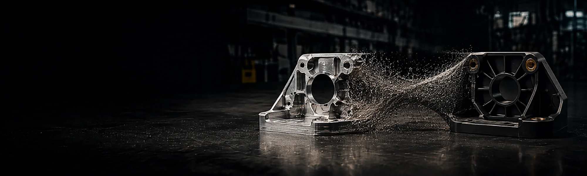
METAL-TO-PLASTIC CONVERSION
REDESIGN THE PART.NOT JUST THEMATERIAL.
Engineering-led assessment of whether a metal component can be redesigned for plastic manufacture — based on function, loads, environment, volumes and tooling.
- FUNCTION FIRSTDefine what the part must do
- MATERIAL BY REQUIREMENTSelect for service conditions
- DESIGN FOR MOULDINGAdapt geometry to the process
- VALIDATE BEFORE PRODUCTIONAgree evidence and acceptance
ENGINEERING DECISION
A BETTER PART —WHEN THE APPLICATION ALLOWS IT.
Metal-to-plastic conversion is not a direct material swap. The opportunity comes from redesigning the component around its function, manufacturing route and expected production life.
LOWER MASS
A plastic design may reduce component weight where the required performance can be maintained.
PART CONSOLIDATION
Ribs, bosses, clips and guides can potentially replace separate pieces and fasteners.
INTEGRATED FEATURES
Shape, colour, insulation and selected surface requirements can be designed into the part.
REPEATABLE SERIAL PRODUCTION
Moulding can provide a consistent route for suitable production volumes.
Not every metal component should be converted. Feasibility comes before tooling.

TOTAL PRODUCT ECONOMICS
COMPARE THE WHOLE PRODUCT.NOT PRICE PER KILOGRAM.
A useful comparison considers material, tooling, machining, finishing, assembly, logistics, annual volume and expected programme life.
| METAL BASELINE | PLASTIC DESIGN |
|---|---|
| Machined or formed geometry | Geometry designed for moulding |
| Fasteners, welds or separate pieces | Potentially integrated ribs, bosses and clips |
| Secondary finishing | Colour, texture or selected finishing |
| Current assembly route | Potential part consolidation |
The result is project-specific. Lower weight or material price alone does not prove feasibility.
A CONTROLLED CONVERSION ROUTE
FROM METAL PART TO VALIDATED PLASTIC DESIGN.
- 01FUNCTIONPurpose & interfaces
- 02LOADSMechanical & environmental
- 03MATERIALPerformance requirements
- 04GEOMETRYDesign for moulding
- 05PROTOTYPEReview & samples
- 06VALIDATEApprove before production
DESIGN FOR MOULDING
THE SAME SHAPE IS RARELYTHE RIGHT ANSWER.
A plastic component carries loads differently from a machined, cast or sheet-metal part. Wall thickness, ribs, radii and interfaces must be developed for both performance and manufacturability.
WALL THICKNESS
Balanced sections and transitions
RIBS & BOSSES
Stiffness and fastening features
DRAFT & RADII
Reliable mould filling and release
GATES & EJECTION
Planned around critical surfaces
TOLERANCES
Defined by function and process
PART INTERFACES
Fits, seals, threads and assembly
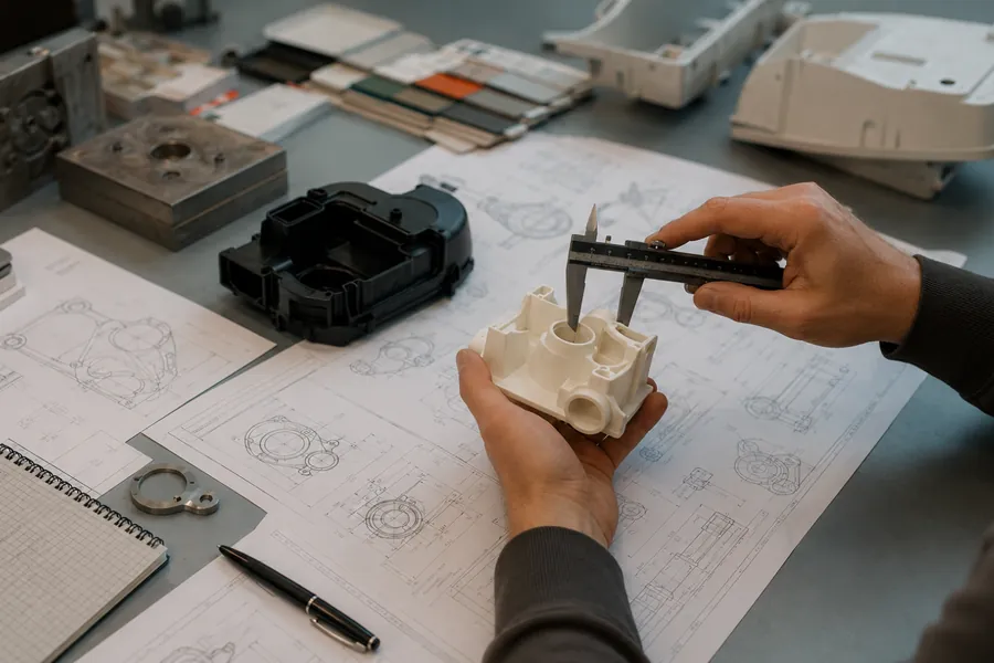
MATERIAL SELECTION
SERVICE CONDITIONSCHOOSE THE POLYMER.
No single polymer replaces metal in every application. Material selection follows the environment and required performance.
- MECHANICAL LOADS
- TEMPERATURE RANGE
- CHEMICAL EXPOSURE
- UV & OUTDOOR USE
- ELECTRICAL & THERMAL NEEDS
- REGULATORY REQUIREMENTS
Unfilled, reinforced or speciality polymers are considered only after the requirements are defined.
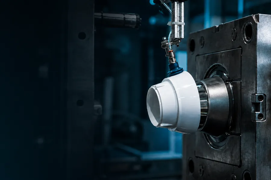
HYBRID SOLUTIONS
PLASTIC WHERE IT ADDS VALUE.METAL WHERE IT IS NEEDED.
Conversion can be complete or hybrid. Insert moulding can retain selected metal functions while plastic creates the surrounding geometry.
- 01
THREADED INSERTS
Keep durable threaded interfaces where required.
- 02
LOCAL REINFORCEMENT
Retain metal at selected highly loaded or wear-sensitive points.
- 03
OVERMOULDED INTERFACES
Combine a metal feature and moulded plastic in one controlled component.
Every insert and interface requires technical review.
EXPLORE INSERT MOULDINGWHAT WE NEED TO ASSESS
START WITH THECURRENT PART.
Send the information that defines what the replacement must achieve.
- 01DRAWING OR 3D MODEL
- 02PART FUNCTION
- 03LOADS & SERVICE CONDITIONS
- 04CRITICAL DIMENSIONS & INTERFACES
- 05EXPECTED ANNUAL VOLUME
- 06REASON FOR CONVERSION
- ISO 9001
- ISO 14001
- AQAP 2110
CONVERSIONQUESTIONS
Potential candidates are parts whose function, loads, temperature, environment, interfaces and expected volumes can be met by a mouldable polymer design. Suitability must be assessed case by case; some metal components should remain metal.
Yes, where the application requires selected metal functions such as threaded, highly loaded or wear-sensitive interfaces. Insert type, positioning, retention and the surrounding plastic geometry must be reviewed together.
Usually not. A plastic part carries loads and is manufactured differently. Wall thickness, ribs, bosses, radii, draft, gates, ejection, tolerances and interfaces often need to be redesigned for moulding.
Send the current drawing or 3D model, the part’s function, mechanical loads, temperature range, chemical or outdoor exposure, critical dimensions and interfaces, expected annual volume and the reason for considering conversion.
START A TECHNICAL REVIEW
LET’S ASSESS YOUR CURRENT PART.
Send the drawing, service conditions, expected volumes and the requirements the replacement must meet.