
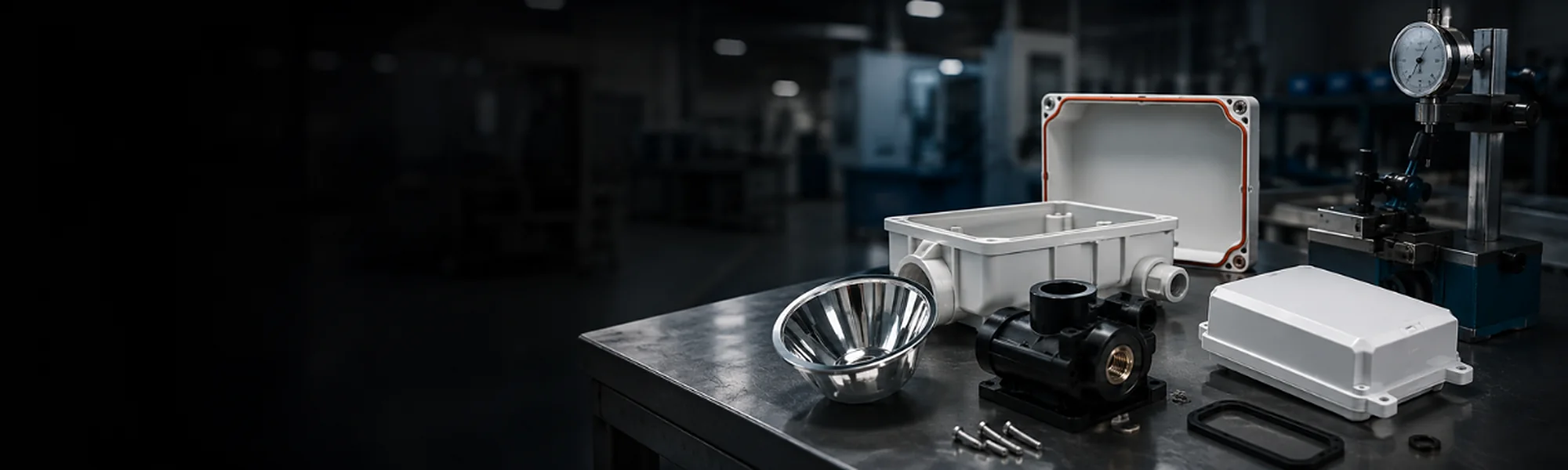
Value-added processes after moulding
From moulded partto finished component.
Combine moulding with finishing, sealing, joining, machining, assembly and packaging within one coordinated manufacturing route.
- FinishingDecorative and functional surfaces
- SealingGaskets and encapsulation
- JoiningControlled component assembly
- CompletionMachining, assembly and packaging
More than a moulded part
Plan the downstreamoperations from the start.
The final finish, seal, joint and assembly requirements can influence material selection, geometry, tooling and inspection. Reviewing the complete component early helps define a practical route from moulding to delivery.
Material
Select material with finishing and joining in mind.
Geometry
Design features for sealing, joining and assembly.
Interfaces
Define contact areas, datums and assembly interfaces.
Acceptance
Plan inspection and performance criteria early.
- Lid(assembled)
- Dispensed gasket(FIPFG)
- Metallized insert(surface finish)
- Moulded housing(base component)
- Internal component(electronics, etc.)
Value-added capabilities
Six processes. One project route.
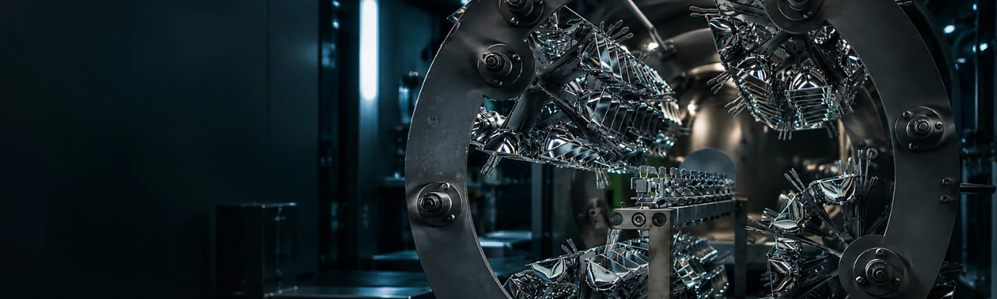
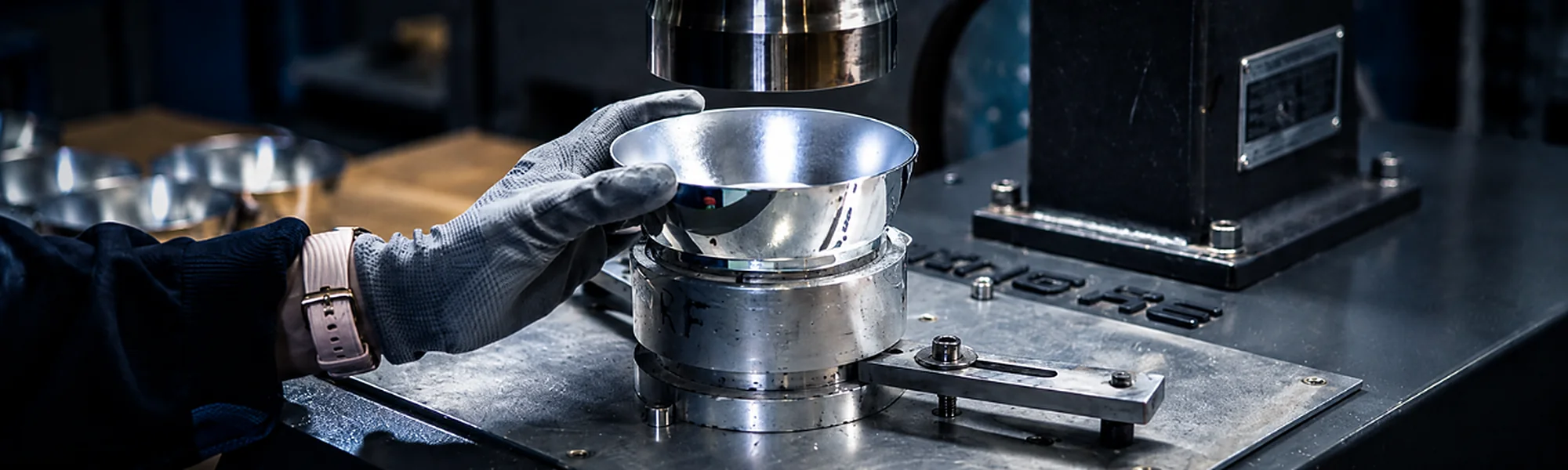
Vacuum metallizing
Reflective or decorative metal-look surfaces on suitable plastic parts.
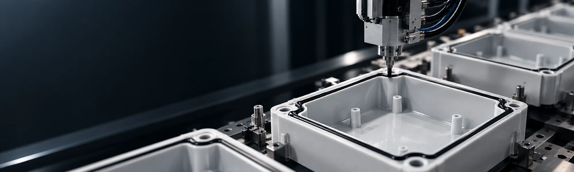
FIPFG gasket sealing
Robot-dispensed 2K PU foam gaskets applied to the defined enclosure geometry.
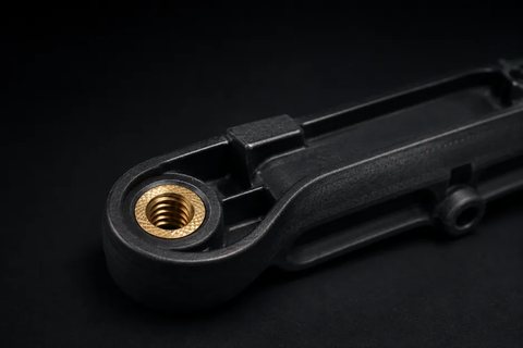
Electronics potting
Encapsulation of electronics within an agreed material, process and acceptance scope.
Ultrasonic welding
Thermoplastic components joined at a designed and supported interface.

CNC machining
Prototypes and post-machining of moulded or formed plastic parts.
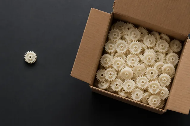
Assembly & packaging
Components, inserts, fasteners and packing completed within the agreed project scope.
A connected manufacturing route
From part data to ready-to-deliver component.
- 01
Define
Function, finish and acceptance
- 02
Mould
Material, geometry and tooling
- 03
Finish
Surface or CNC operations
- 04
Seal / Join
Gasket, potting or welding
- 05
Assemble
Components and checks
- 06
Deliver
Approved packing scope
The exact route is selected for the component, application and agreed acceptance criteria.
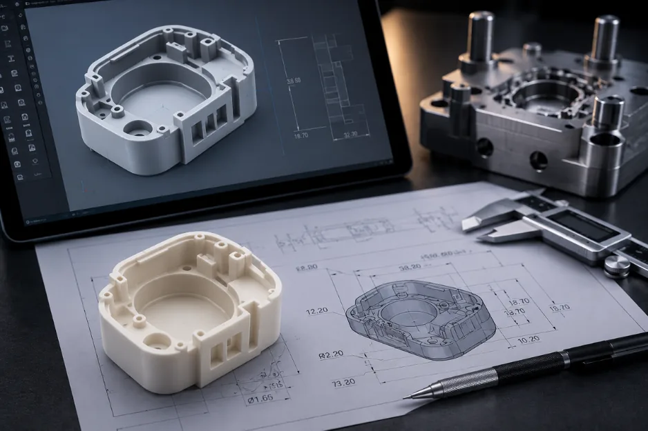
The final function startswith the drawing.
Downstream processes are most reliable when their interfaces are designed into the part rather than added as an afterthought.
Surface & material
Confirm compatibility with the selected finish or process.
Sealing geometry
Define the gasket path, groove and mating surfaces.
Joining interface
Review material pairing, energy path and part support.
Machining datums
Identify post-machined features and reference surfaces.
Assembly content
List inserts, fasteners, electronics and supplied parts.
Packaging needs
Protect appearance and function through delivery.
Process suitability and final performance are confirmed for the specific part, material, geometry and project requirements.
One partner.Fewer handovers.
Keeping complementary operations within one coordinated route can simplify communication, part movement and responsibility between stages.
- One project interface
- Aligned production stages
- Acceptance defined for the finished component
- FINISH
- SEAL
- JOIN
- MACHINE
- ASSEMBLE
- PACK
Quality belongs to the complete part
Define what must beaccepted — and where.
Inspecting the finished component confirms that all processes have been completed correctly and that the part meets the agreed requirements.
Appearance
Visible surfaces, colour and finish criteria
Dimensions
Critical features and post-process geometry
Function
Assembly, joint, seal or other agreed checks
Documentation
Customer-specific records within the project scope
ISO 9001 | ISO 14001 | AQAP 2110
Any leak-tightness, IP rating, adhesion, reflectivity or joint-strength target must be defined and verified for the complete component under agreed conditions.
Start with the complete requirement
Send the part data —and the result you need.
The more complete the information, the faster a practical and accurate manufacturing route can be defined.
Part & process data
- 2D drawings and 3D models
- Material and expected quantity
- Required surface or value-added process
- Critical dimensions and visible surfaces
Finished component requirements
- Mating parts and assembly content
- Functional and environmental targets
- Appearance and acceptance criteria
- Inspection, documentation and packaging scope
Not sure which route fits? Send the available data and Vesimentor can review the project scope with you.
Value-added processQuestions
The manufacturing route can combine moulding with suitable finishing, sealing, potting, ultrasonic welding, CNC machining, assembly and packaging. The exact combination is selected according to the component, material, geometry and agreed acceptance requirements.
Consider downstream operations during the initial part and tooling review. Surface requirements, gasket paths, joining features, machining datums and assembly interfaces can influence material selection and component geometry.
No. FIPFG creates a robot-dispensed foam gasket along a defined sealing path. Electronics potting encapsulates or protects components within a cavity. Each process requires its own material, geometry and acceptance review.
Provide available 2D drawings and 3D models, material information, expected quantities, required processes, mating parts and assembly content, critical dimensions, visible surfaces, functional targets and acceptance criteria.
Have a component that needs more than moulding?
Let’s define the complete manufacturing route.
Share the drawing, material, expected quantity, required finish or assembly and the acceptance criteria for the finished part.