
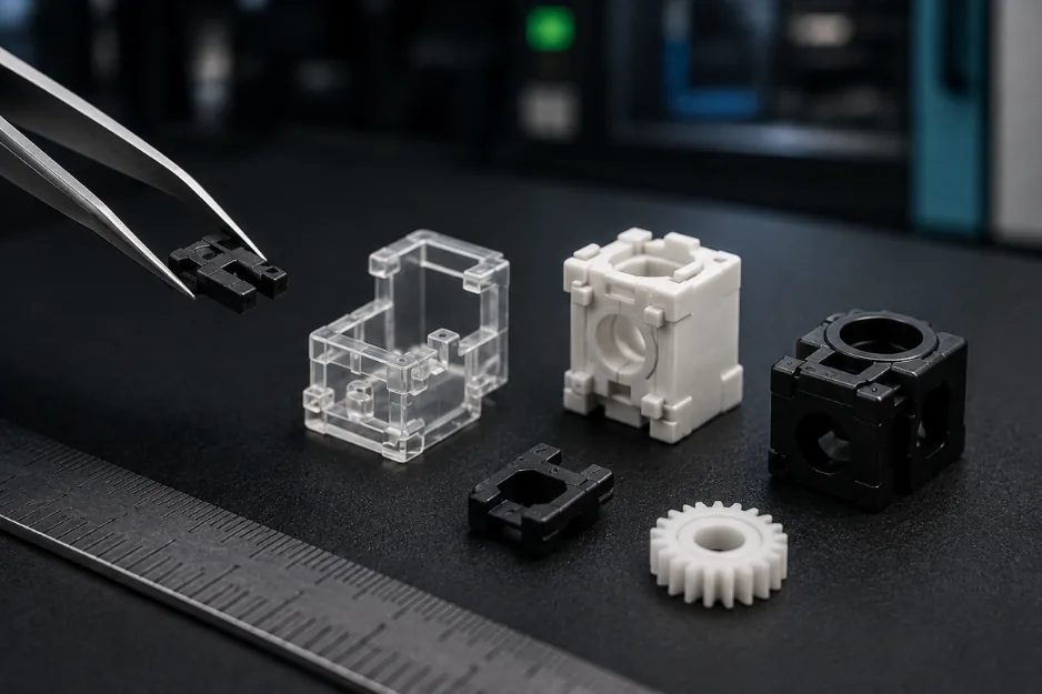
Small & Precision Injection Moulding
Small parts.Serious control.
Injection moulding for compact technical components from about 1 g — reviewed around geometry, material, tooling, inspection and repeatable series production.
- From about 1 gDepending on material and part design
- DFM + toolingPart and tool reviewed together
- Sample approvalAgreed dimensions and functions
- One supply scopeMoulding, finishing and assembly
Small size, full engineering
Compact components stillrequire the complete process.
Small components are reviewed against the same practical questions as larger mouldings: intended function, material, geometry, tooling, expected quantity and acceptance criteria. At a smaller scale, fine features and critical interfaces become especially important.
Fine features
Review geometry and fill
Critical dimensions
Define what must be controlled
Material behaviour
Match grade and application
Handling & assembly
Plan the downstream route
Design for moulding at small scale
The drawing mustshow what matters.
Identify the features, dimensions and functions that determine whether the component is acceptable.
Walls & transitions
Review thin sections, ribs and thickness changes.
Flow & fill
Assess how the selected material reaches fine features.
Parting & ejection
Plan surfaces, draft and release from the tool.
Critical tolerances
Mark only the dimensions that drive function.
Material & shrinkage
Review the specified grade with the geometry.
Mating interfaces
Provide related parts and assembly conditions.
Feasibility and achievable results are assessed for the specific part, material and tooling concept.
A controlled project route
From part data torepeatable production.
- 01
Define
Function, environment and quantity
- 02
Review
Geometry, material and critical features
- 03
Tool
Tool concept and production approach
- 04
Sample
Parts for review and measurement
- 05
Approve
Agreed dimensions and functions
- 06
Produce
Serial moulding and required follow-up
Inspection and documentation requirements are agreed according to the project.
Part and tool design
Precision starts withclear input data.
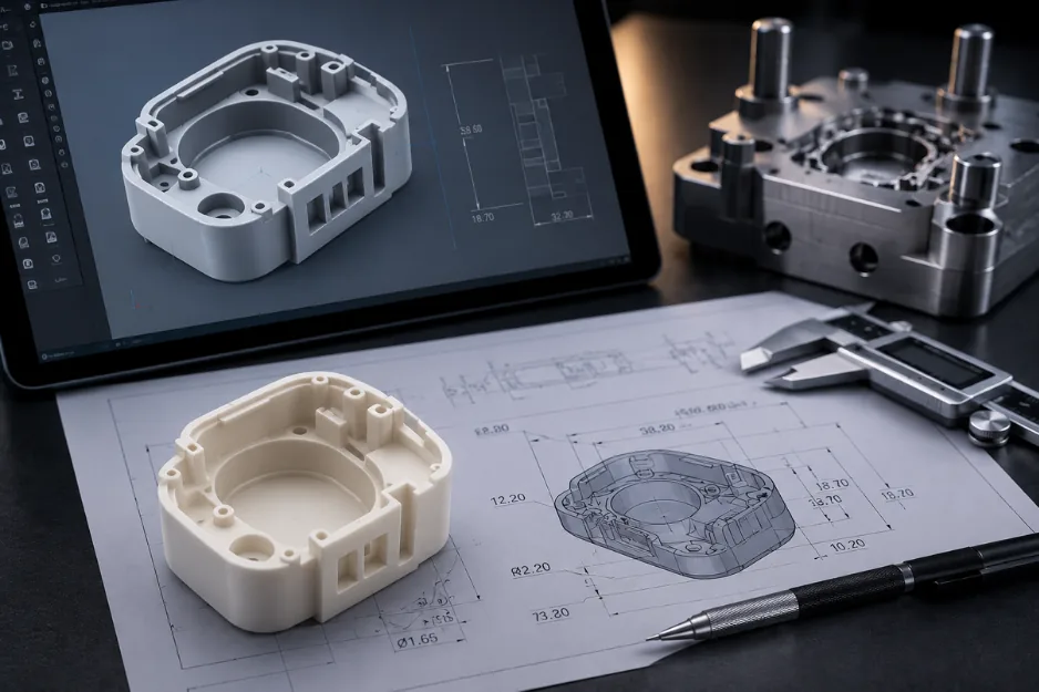
Provide the 2D drawing and 3D model together. The drawing should identify critical dimensions, functional surfaces, material requirements and any interfaces that affect fit or assembly.
- 01
Geometry
Fine features, sections and draft
- 02
Material
Exact grade where known
- 03
Function
Loads, fit and operating conditions
- 04
Acceptance
What must be checked on samples
Do not apply the same tolerance to every dimension. Define the characteristics that are genuinely critical to the component.
Sampling & series production
Approve what matters.Repeat what was agreed.
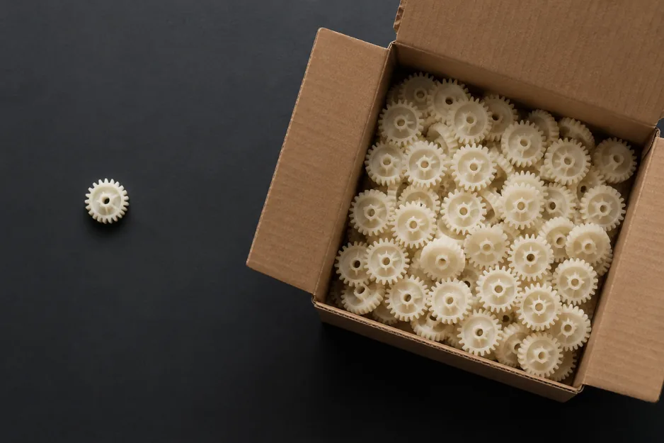
Before serial production, samples are reviewed against the agreed drawing, functional requirements and inspection scope. The production approach is then maintained around the approved part and project requirements.
Reference data
Approved drawing and material
Sample review
Defined dimensions and functions
Documentation
Customer-specific scope where required
Serial supply
Packaging and delivery requirements agreed
- ISO 9001
- ISO 14001
- AQAP 2110
Beyond the moulding step
Plan the finished componentfrom the start.
A small moulded part may also require surface finishing, machining, sealing, joining or assembly. Include these requirements at the enquiry stage so that the complete route can be reviewed.
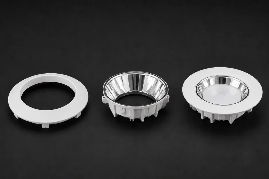
Metallizing
Selected decorative or functional surface treatment.
Machining
Post-processing where the agreed geometry requires it.
Sealing & joining
FIPFG, potting or ultrasonic welding where suitable.
Assembly & packaging
Completion within the agreed supply scope.
Compatibility of downstream operations is assessed with the material, component design and intended use.
What to send for a review
Start with the part, functionand critical features.
Part data
- 2D drawing and 3D model
- Material grade where known
- Critical dimensions and surfaces
- Mating components or assembly layout
- Existing tooling information
Project requirements
- Intended function and environment
- Expected annual quantity
- Required sample checks
- Documentation requirements
- Finishing, assembly and packaging scope
Precision mouldingquestions
Fine features, thin sections, critical interfaces and limited space for parting or ejection can make a compact component demanding. The complete combination of geometry, material, tooling, function and acceptance criteria must therefore be reviewed.
Identify the dimensions and surfaces that directly affect function, fit or assembly instead of applying the same tolerance to every feature. Provide the 2D drawing, 3D model and related mating-component information where available.
Samples are reviewed against the agreed drawing, material, critical dimensions, functional requirements and inspection scope. The exact approval criteria and documentation are defined according to the project.
Where suitable for the component and agreed project scope, subsequent operations may include metallizing, machining, FIPFG gasketing, potting, ultrasonic welding, assembly and packaging. Include these requirements at the enquiry stage so that compatibility can be reviewed.
Have a small technical part in mind?
Send the drawing and project requirements.
Share the 2D drawing or 3D model, material, critical dimensions, expected quantity and any finishing or assembly requirements. Our team will review the proposed manufacturing route.