

FIPFG Foam Gasketing & Electronics Potting
Seal the joint.Protect the assembly.
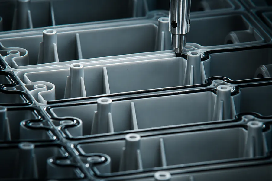
Robot-applied FIPFG foam gaskets for moulded housings — reviewed around the gasket path, joint geometry, compression, closing arrangement and required enclosure performance.
- Applied directlyFoam gasket dispensed onto the component
- Robot dispensingGasket path reviewed with the part
- Complete enclosureJoint, closing and interfaces considered together
- One supply scopeMoulding, sealing and assembly
The gasket is part of the enclosure
Design the joint as one system.
A sealing result depends on the housing, gasket, mating surface and closing arrangement working together. The gasket path, material, compression and operating environment must therefore be reviewed as a complete joint.
Gasket path
Continuous route and transitions
Joint geometry
Landing surfaces and available space
Compression
Controlled by the assembled joint
Operating conditions
Environment defined for the application
Gasket and part feasibility are confirmed for the individual project.
Designing the sealing joint
The drawing must definehow the enclosure closes.
Provide the complete joint and mating-part information so that the proposed gasket route can be reviewed.
Sealing path
Mark the full route, corners, starts and transitions.
Landing surface
Define the surface supporting the gasket.
Mating component
Provide the cover and contact geometry.
Closing arrangement
Show fasteners, clips and support points.
Critical interfaces
Identify openings, inserts and crossing features.
Environment
State temperature, chemicals, cleaning and exposure.
A gasket cannot compensate for an enclosure or closing arrangement that has not been designed for the required result.
A controlled project route
From housing data to applied gasket.
- 01
Define
Protection target and operating conditions
- 02
Review
Housing, gasket path and mating component
- 03
Prepare
Part and process route agreed
- 04
Dispense
Foam gasket applied to the component
- 05
Approve
Samples reviewed against agreed criteria
- 06
Complete
Assembly and verification scope agreed
Material, process and inspection requirements are defined according to the project.
Enclosure protection
The IP rating belongs tothe complete assembly.
An IP rating applies to the finished enclosure, not to the gasket or dispensing process alone. The housing, cover, gasket compression, fasteners, openings and interfaces all affect the result.
- Housing
- Mating cover
- Gasket path
- Compression
- Fasteners
- Openings & interfaces
The required protection level must be verified on the finished assembly under the specified conditions.
Two different processes
Foam gasketing and pottingsolve different tasks.
FIPFG foam gasketing
Robot-dispensed foam follows a defined path on the housing and forms a compressible gasket for the assembled joint.
- Applied along a sealing path
- Works with the mating component
- Compression occurs in the closed assembly
Electronics potting
Potting or encapsulation fills a defined area around selected components. Compound, layout, depth and operating conditions must be reviewed separately.
- Defined encapsulation area
- Component layout and clearances
- Compound requirements specified for the application
Potting is not the same process as FIPFG foam gasketing. Requirements and acceptance criteria must be specified separately.

Applied directly to the component
The gasket follows the part.
Robot dispensing allows the gasket path to follow the housing geometry. Corners, transitions, start and finish areas and nearby features must still be reviewed with the component.
Path continuity
Review the complete gasket route
Corners & changes
Assess tight radii and transitions
Part location
Support and repeatable positioning
Handling
Protect the gasket before assembly
Moulding, sealing and assembly
Plan the complete enclosurefrom the start.
When the housing, gasket and downstream operations are considered together, interfaces can be reviewed before the project reaches serial production.
Plastic moulding
Housing material and geometry developed for the component.
Machining
Post-processing where the agreed geometry requires it.
FIPFG gasketing
Gasket path applied to the approved housing.
Potting or joining
Separate downstream scope where suitable.
Assembly & packaging
Completion within the agreed project scope.
What to send for a review
Start with the housing, jointand required result.
Part & joint data
- 2D drawing and 3D model
- Housing and mating-component materials
- Complete gasket path
- Joint and closing arrangement
- Critical openings and interfaces
Project requirements
- Operating environment
- Target enclosure protection
- Expected annual quantity
- Required sample checks
- Assembly, testing and packaging scope
For potting enquiries, include the component layout, encapsulation area and compound requirements.
- ISO 9001
- ISO 14001
- AQAP 2110
FIPFG & pottingQuestions
FIPFG is a process in which a foam gasket is dispensed directly along a defined path on the component. The gasket works as part of the assembled joint, together with the housing, mating component, compression and closing arrangement.
No. An IP rating applies to the complete finished enclosure, not to the gasket or dispensing process alone. The housing, cover, gasket compression, fasteners, openings and other interfaces all affect the result. The required protection level must be verified on the finished assembly under the specified conditions.
Provide the housing and mating-component drawings or models, gasket path, joint geometry, closing arrangement, fastener or clip locations, critical openings, materials and operating environment. Include the required enclosure-protection target and acceptance criteria.
FIPFG creates a compressible gasket along a defined sealing path. Potting or encapsulation fills a defined area around selected components. Potting requires separate information about the component layout, encapsulation area, compound requirements and operating conditions.
Have a housing or sealing project in mind?
Send the joint and performance requirements.
Share the housing drawing, mating component, gasket path, closing details, operating environment and target protection level. For potting, include the component layout and compound requirements.