
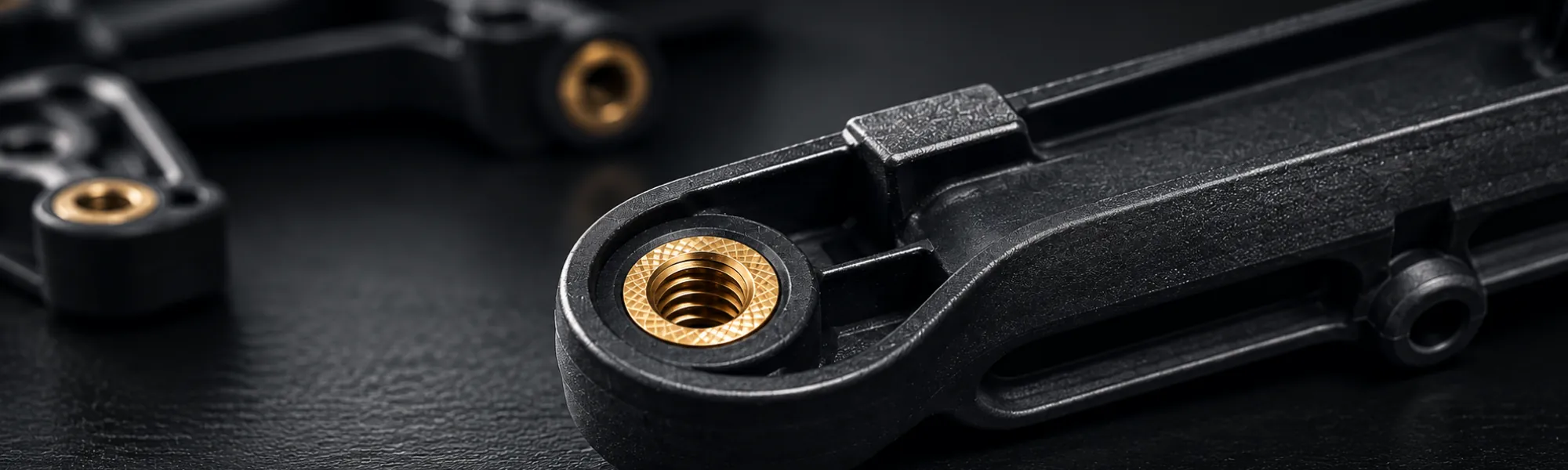
Overmoulding & Insert Moulding
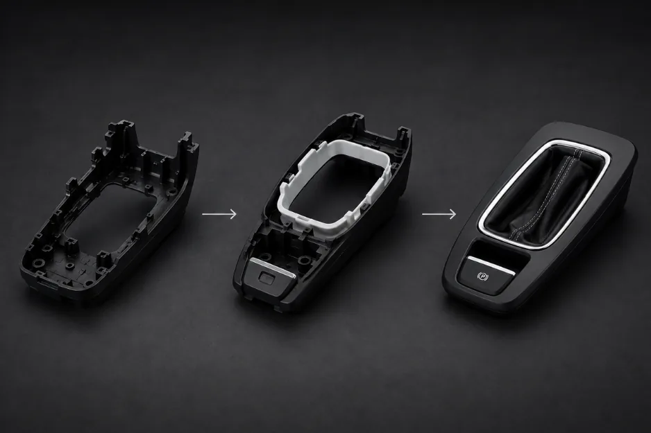
Combine materials.Integrate function.
Plastic around a metal insert or a first-shot core – reviewed as one system of materials, interface geometry, tooling and production requirements.
- Two routesOvermoulding and insert moulding
- Metal + plasticSpecified functional inserts
- Multi-materialPlastic around a first-shot core
- One scopeFrom tooling to finished assembly
Two related processes
Choose the routethe component requires.
Overmoulding and insert moulding both combine elements during moulding, but the part architecture, material interface and tooling requirements are different.
Overmoulding
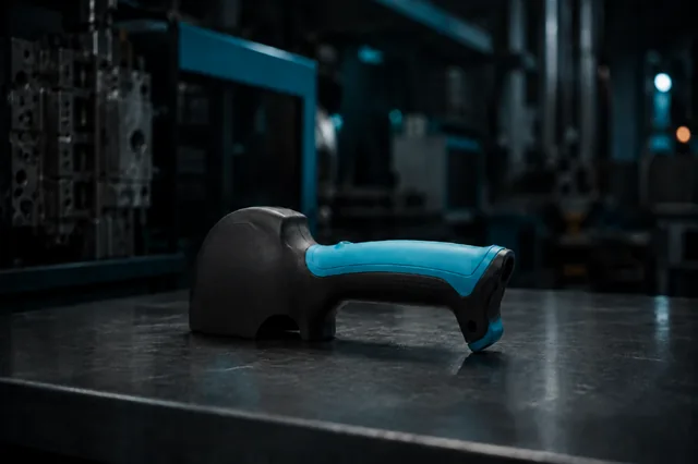
Plastic is moulded around an existing component or first-shot core. The material combination, geometry and interface requirements determine whether the route is suitable.
- First-shot or existing core
- Material-pair review
- Interface designed for the function
Insert moulding
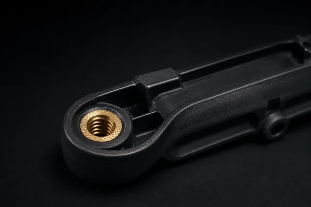
A specified insert is positioned in the tool and incorporated into the plastic part during moulding. Insert geometry, retention and location must be considered in the part and tool design.
- Specified functional insert
- Tool positioning and support
- Retention designed into the part
The processes are not interchangeable. Suitability is reviewed against the component, materials, tooling and required result.
Design the interface
The connection betweenmaterials is part of the design.
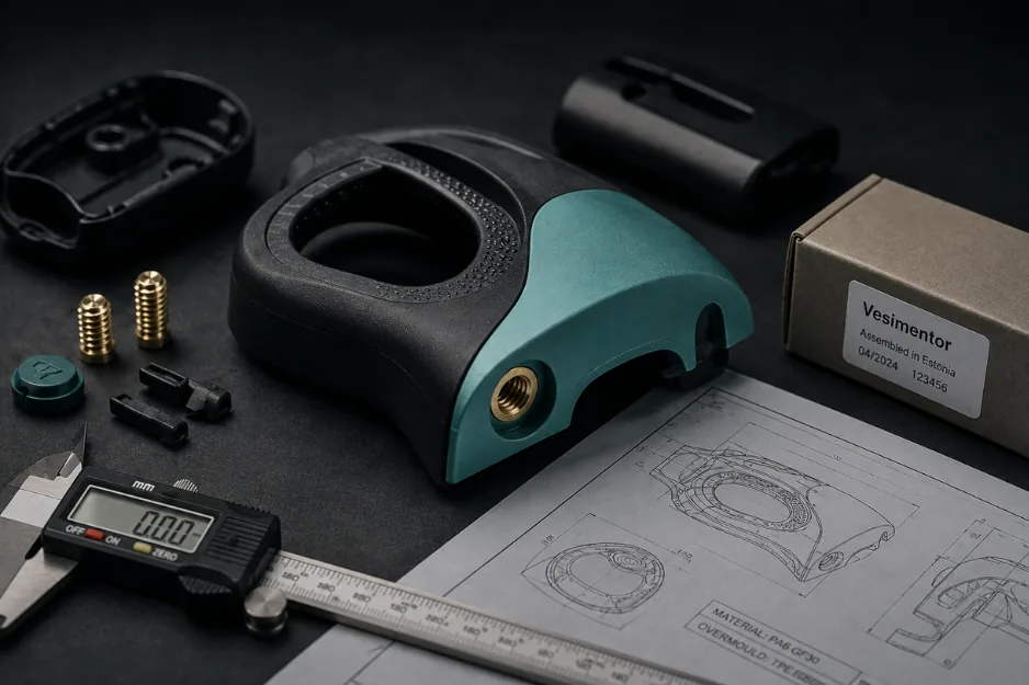
A combined-material component must be reviewed as a complete system. The interface may rely on material adhesion, mechanical retention or a combination of both, depending on the materials, geometry and service conditions.
Material pairing
Grades and compatibility
Retention geometry
Undercuts, features and load path
Insert specification
Material, surface and dimensions
Position & support
Location during moulding
Moulding conditions
Heat, pressure and movement
Critical interfaces
Dimensions, appearance and assembly
Specific adhesion, pull-out strength, sealing performance or service life must be defined and verified for the application.
A controlled project route
From component ideato repeatable production.
- 01
Define
Function, loads and service conditions
- 02
Review
Part, insert and interface geometry
- 03
Select
Materials and insert specification
- 04
Tool
Positioning, retention and sampling
- 05
Validate
Samples and agreed acceptance criteria
- 06
Produce
Serial moulding and subsequent operations
Quality requirements and documentation are agreed according to the project.
Material pairing
Compatibility must bereviewed, not assumed.
Base or core
The existing component or first-shot core, including its material and surface.
Second material
The material moulded around the core or insert and its processing requirements.
Interface
The geometry and contact area that transfer the required function or load.
Service conditions
Temperature, chemicals, movement, wear, appearance and expected use.
Material grades should be specified where known. If they are not fixed, provide the functional and environmental requirements so that suitable options can be reviewed.
Insert moulding
Function built intothe moulded component.
- 01
Insert data
Material, dimensions, surface condition and functional requirement.
- 02
Retention
Features that resist the intended loading and movement.
- 03
Position
Location, orientation and support in the mould.
- 04
Acceptance
Critical dimensions, appearance and functional verification.
Threaded elements and other specified functional inserts are reviewed with the part and tool design.
Subsequent operations
Plan the complete part,not only the moulding step.
Machining
Post-processing where the agreed geometry requires it.
Metallizing & finishing
Selected surface operations assessed with the material and part.
Sealing & joining
FIPFG gasketing, potting or ultrasonic welding where suitable.
Assembly & packaging
Component completion within the agreed supply scope.
Downstream operations must be included in the enquiry so their compatibility can be reviewed with the combined-material design.
What to send for a review
Start with theinterface requirements.
Part & insert data
- 2D drawing or 3D model
- Insert or first-shot core specification
- Material grades where known
- Critical dimensions and surfaces
- Mating components and assembly layout
Project requirements
- Intended function and loads
- Operating environment
- Expected annual quantity
- Existing tooling information
- Required inspection and documentation
- Finishing, sealing or assembly scope
- ISO 9001
- ISO 14001
- AQAP 2110
- Customer-specific documentation where required
Combined-material
Questions
In overmoulding, plastic is moulded around an existing component or a first-shot core. In insert moulding, a specified insert is positioned in the mould and incorporated into the plastic part during the moulding cycle. The suitable route depends on the component architecture, materials, interface and tooling requirements.
Compatibility is reviewed using the exact material grades, processing requirements, interface geometry and expected service conditions. Where required, the proposed solution is evaluated through samples and agreed acceptance criteria rather than assumed from the material names alone.
Yes. Customer-specified inserts can be reviewed for the application. Please provide the insert material, dimensions, surface condition, tolerances and functional or handling requirements together with the part data.
Where suitable for the component and agreed project scope, subsequent operations may include machining, metallizing, FIPFG gasketing, potting, ultrasonic welding, assembly and packaging. These requirements should be included in the initial enquiry.
Have a combined-material part in mind?
Send the part, insert and requirements.
Share the drawing, material or insert specification, annual quantity and interface requirements. Our team will review the proposed manufacturing route.