
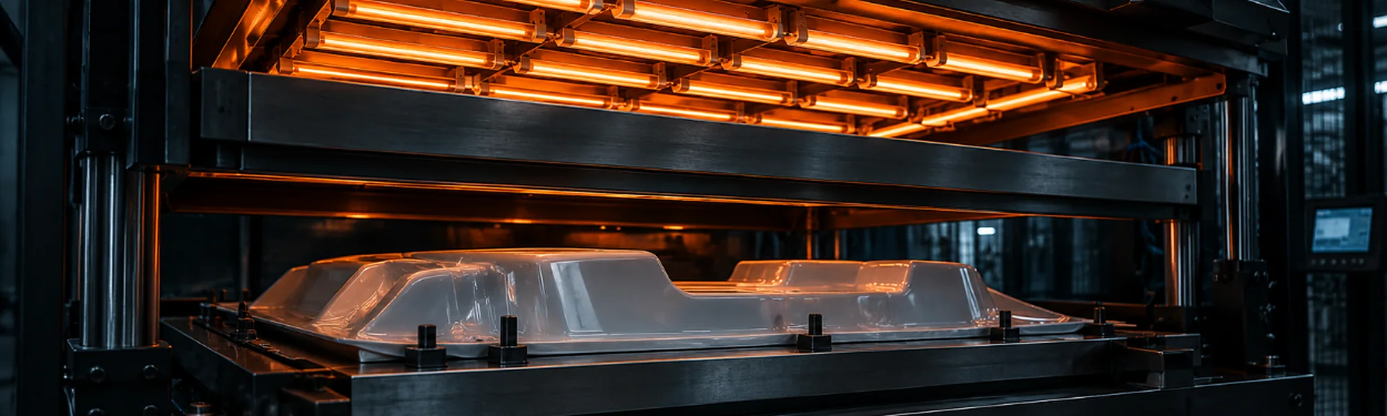
Vacuum forming of plastic sheet
Form the sheet.Finish the part.
Custom covers, panels and housings from thermoformable plastic sheet — reviewed from geometry, material and tooling through forming, trimming and final assembly.
- Thermoplastic sheetCovers, panels and housings
- Formed by vacuumHeated sheet drawn onto the mould
- Trimmed to requirementEdges, openings and mounting features
- One project routeTooling, forming and finishing
The right route for the part
Review the sheet, tool andgeometry together.
Vacuum forming starts with a flat thermoplastic sheet and a defined mould. Part depth, radii, draft, material, surface finish and trimming requirements must be considered as one manufacturing route.
Overall size & depth
Define the formed envelope
Draft & release
Plan removal from the mould
Radii & transitions
Avoid abrupt geometry changes
Sheet & finish
Specify grade, colour and surface
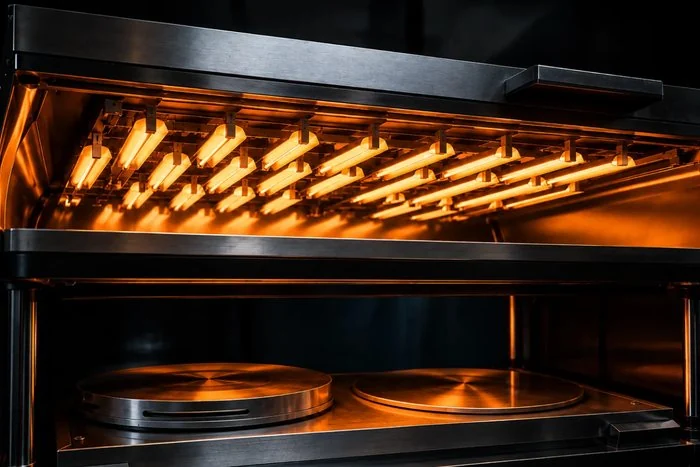
A general machine size does not establish feasibility for a particular design.
The vacuum forming process
From flat sheet to trimmed component.
- 01
Define
Function, dimensions and finish
- 02
Review
Geometry, sheet and production quantity
- 03
Tool
Mould concept prepared for the part
- 04
Heat & form
Sheet shaped over the mould by vacuum
- 05
Cool & release
Formed part removed from the tool
- 06
Trim & finish
Edges, openings and follow-up operations
Tooling and process requirements are defined according to the geometry, material and project scope.
Design for vacuum forming
The forming directionshapes the design.
The complete surface is created from one sheet, so geometry must support forming, release and the required finished result.
Forming depth
Review depth against footprint and material.
Draft angles
Allow the part to release from the mould.
Radii & corners
Use transitions suited to sheet forming.
Wall distribution
Consider how the sheet stretches across the part.
Trim line
Define the final edge and reference surfaces.
Undercuts & features
Identify geometry requiring a separate solution.
Wall distribution, detail reproduction and dimensional results depend on the specific geometry, sheet and tooling concept.
Forming and trimming
The formed shape is onlythe first step.
After forming and cooling, the component is released and trimmed to the agreed outline. Openings, cut-outs and mounting features are included according to the project.
1. Heat the sheet
2. Form over the mould
3. Cool & release
4. Trim the part
Trimming requirements and reference points must be identified on the drawing.
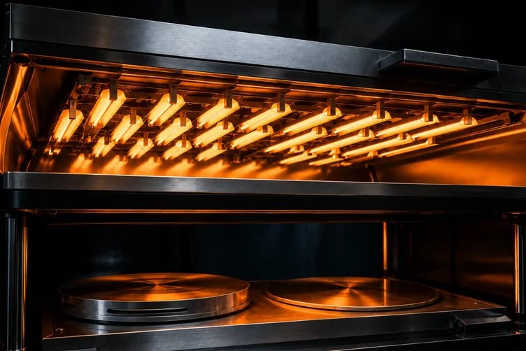
Tooling & production review
The tool must match the partand quantity.
Tooling requirements depend on geometry, material, finish and expected production volume. Existing tools, prototypes and new production tooling must be reviewed against the intended route.
Tool surface
Supports the required formed appearance
Vacuum route
Defined for the geometry
Part release
Draft and tool access considered
Production scope
Quantity and repeat requirements agreed
Sheet material & surface
Specify the material aspart of the result.
Provide the proposed sheet material and exact grade where known. Formability, appearance, operating environment and any downstream finishing must be reviewed together.
Material grade
State the specified thermoformable sheet.
Colour & texture
Define visible-surface expectations.
Operating environment
Describe temperature, chemicals, cleaning and exposure.
Downstream finish
Include metallizing, coating or assembly requirements.
Materials such as ABS, PC or PMMA may be considered where suitable, but grade and project compatibility must be confirmed.
From formed sheet to finished component
Plan every operationbefore tooling.
A vacuum-formed component may require trimming, CNC machining, surface finishing, sealing or assembly. Include the complete scope at the enquiry stage so that interfaces can be reviewed together.
Vacuum forming
Thermoplastic sheet shaped over the approved mould.
Trimming & CNC
Final edges, openings and mounting features.
Surface finishing
Selected finish assessed with the sheet material.
Sealing & joining
FIPFG or joining route where suitable.
Assembly & packaging
Completion within the agreed project scope.
What to send for a review
Start with the part envelope, sheet and finished requirements.
Part & material data
- 2D drawing and 3D model
- Overall dimensions and forming depth
- Proposed sheet material and grade
- Critical surfaces and trim line
- Mating parts and mounting details
Project requirements
- Intended use and environment
- Expected annual quantity
- Colour, texture and appearance
- Openings and machining scope
- Finishing, assembly and packaging
ISO 9001|ISO 14001|AQAP 2110
Vacuum formingQuestions
A thermoplastic sheet is heated and drawn onto a mould by vacuum. After forming and cooling, the component is released and trimmed to the agreed outline. The exact tooling and process route depend on the part geometry, material and project scope.
Suitability depends on the overall footprint, forming depth, draft, radii, transitions, trim line, sheet material and tooling concept. Undercuts and other difficult features must be identified so that an appropriate solution can be reviewed.
After forming, the component is trimmed to its final outline. Openings, cut-outs and mounting features can be included according to the agreed drawing and manufacturing scope. Trim lines and reference points should be clearly defined in the part data.
Where suitable and included in the agreed project scope, subsequent operations may include CNC machining, vacuum metallizing, sealing, joining, assembly and packaging. These requirements should be identified during the initial review.
Have a cover, panel or housing in mind?
Send the drawing and sheet requirements.
Share the overall dimensions, forming depth, proposed material, expected quantity and required finish. Include any trimming, machining, metallizing, sealing or assembly requirements.